


Description
The 16×2 Alphanumeric LCD Display Module is equally popular among hobbyists and professionals for its affordable price and easy to use nature. As the name suggests the 16×2 Alphanumeric LCD can show 16 Columns and 2 Rows therefore a total of (16×2) 32 characters can be displayed. Each character can either be an alphabet or number or even a custom character. This particular LCD gas a green backlight, you can also get a Blue Backlight LCD to make your projects stand our and visually appealing, apart from the backlight color both the LCD have the same specifications hence they can share the same circuit and code. If your projects require more characters to be displayed you can check the 20×4 Graphical LCD which has 20 Columns and 4 Rows and hence can display up to 80 characters.
SPECIFICATIONS OF 16X2 LCD DISPLAY MODULE:
- Operating Voltage: 4.7V to 5.3V
- Operating Current 1mA (without backlight)
- Can display (16×2) 32 Alphanumeric Characters
- Custom Characters Support
- Works in both 8-bit and 4-bit Mode
The 16×2 LCD pinout diagram is shown below. As you can see the module has (from right) two power pins Vss and Vcc to power the LCD. Typically Vss should be connected to ground and Vcc to 5V, but the LCD can also operate from voltage between 4.7V to 5.3V. Next, we have the control pins namely Contrast (VEE), Register Select (RS), Read/Write (R/W) and Enable (E). The Contrast pin is used to set the contrast (visibility) of the characters, normally it is connected to a 10k potentiometer so that the contrast can be adjusted. The Read/Write pin will be grounded in most cases because we will only be writing characters to the LCD and not read anything from it. The Register Select (RS) and Enable pin (E) pin are the control pins of the LCD and will be connected to the digital pins GPIO pins of the microcontroller. These pins are used to instruct the LCD where place a character when to clear it etc.

From DB0 to DB7 we have our eight Data Pins which are used to send information about the characters that have to be displayed on the LCD. The LCD can operate in two different modes, in the 4-bit Mode only pins DB4 to DB7 will be used and the pins DB0 to DB3 will be left idle. In 8-bit Mode, all the eight-pin DB0 to DB7 will be used. Most commonly the 4-bit mode is preferred since it uses only 4 Data pins and thus reduces complexity and GPIO pin requirement on the microcontroller. Finally, we have the LED+ and LED- pins which are used to power the backlight LED inside our Display module. Normally the LED+ pin is connected to 5V power through a 100 ohm current limiting resistor and the LED- pin is connected to Ground.
PIN DESCRIPTION OF 16X2 LCD DISPLAY:
|
Pin No. |
Pin Symbol |
Pin Name |
Connection Description |
|
1 |
VSS |
Ground |
Connected to Ground |
|
2 |
VCC |
Power |
Connected to Power (Typically 5V) |
|
3 |
VEE |
Contrast |
Connected to potentiometer 10k to control contrast |
|
4 |
RS |
Register Select |
Connected to Microcontroller |
|
5 |
R/W |
Read/Write |
Connected to Ground |
|
6 |
E |
Enable |
Connected to Microcontroller |
|
7 |
DB0 |
Data Pin 0 |
Connected to Microcontroller based on 4-bit or 8-bit Working Mode |
|
8 |
DB1 |
Data Pin 1 |
|
|
9 |
DB2 |
Data Pin 2 |
|
|
10 |
DB3 |
Data Pin 3 |
|
|
11 |
DB4 |
Data Pin 4 |
|
|
12 |
DB5 |
Data Pin 5 |
|
|
13 |
DB6 |
Data Pin 6 |
|
|
14 |
DB7 |
Data Pin 7 |
|
|
15 |
LED+ |
LED Positive |
Connected to 5V through 100 ohm Resistor |
|
16 |
LED- |
LED Negative |
Connected to Ground |
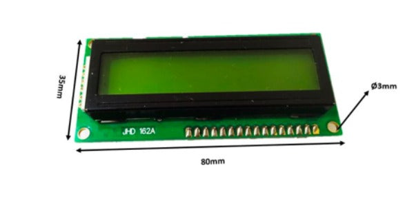
The dimensions of 16×2 LCD display is shown below


Reviews
There are no reviews yet.